Before we dive into contact configurations, it is important to understand the definition of a push button switch. Push buttons are types of switches that are operated by pressing a button to make or break an electrical connection. They are commonly used in electronic devices and control systems to initiate an action or process with a simple push. We have various blog posts covering different types of switches, browse these here.
Navigating the terminology associated with switches can be challenging at times. Positioned on the underside of most switches are a series of terminals, which serve as the connection points enabling the switch to be incorporated into your circuits. Each terminal functions uniquely, and grasping their specific roles is essential.
The Essential Components in Your Circuit:
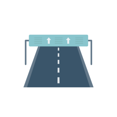
C (Common): Consider the C terminal as the primary power conduit. Can be compared to the main road, as it serves as the road for your electricity to travel from your battery or power source (typically the positive (+) side) to reach your switch.
NO (Normally Open): Visualise a doorbell, when the button is at rest and not being pressed, the doorbell remains silent. This is because the circuit is open, similar to a broken wire. The NO terminal operates like the doorbell button, as it is “normally open,” meaning that no electricity passes through it until the button is pressed. Pressing the button closes the circuit, much like triggering a doorbell button to produce a ring.
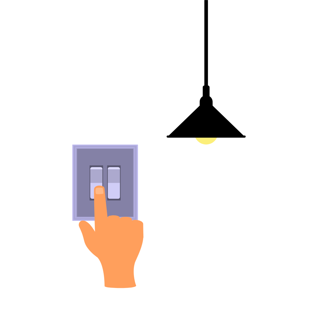
NC (Normally Closed): Consider a light switch that is in the “on” position. In this state, electricity is actively passing through the wires, and the light is illuminated. The NC terminal operates similarly—it is “normally closed,” signifying that electricity can freely pass through it until its flow is interrupted. When the button is pressed, it parallels the action of switching off the light, consequently disrupting the circuit and cease the flow of electricity.
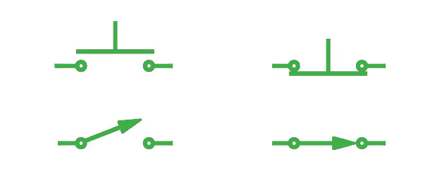
Our diagram shows symbols comparing NO vs NC contacts. NO (Left) NC (Right).
(LED Positive) & – (LED Negative): Numerous push button switches are designed with integrated LEDs to offer visual cues. The two terminals denoted as + and – are designated for the LED. The + terminal links to the positive (+) side of the LED, while the – terminal connects to the negative (-) side, allowing you the ability to regulate the LED’s illumination.
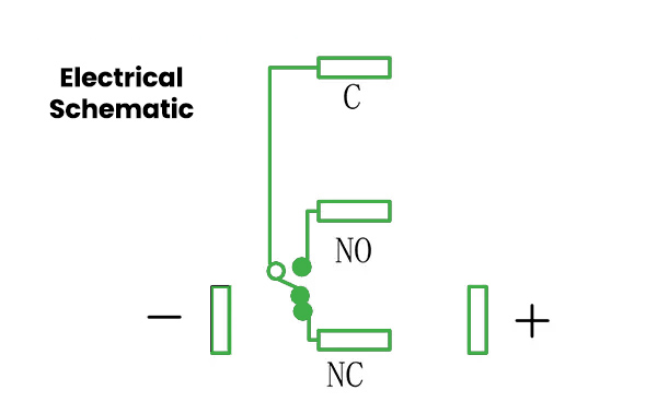
EXAMPLE:
5 Pin Electrical Schematic
Final Thoughts
In conclusion, mastering the fundamentals of contact configurations for switches is essential for anyone delving into the world of electronics. Understanding how these configurations work and their applications, allows beginners to navigate the switch terminals with confidence.
Interested in our products? Speak to us today!
How to place an order?
We operate Monday – Thursday (8 am – 5 pm) and Fridays (8 am – 4.30 pm)
Call us on +44 (0) 1234 213600 to speak to our Sales Engineers or e-mail us

 & – (LED Negative) Numerous push button switches are designed with integrated LEDs to offer visual cues. The two terminals denoted as + and – are designated for the LED. The + termi")